Introduction
The BlueBerry or DEVCC are a family of embedded application development PCBs which cater to the wide variety of PIC family packages available. Since PICs are available in 8, 14, 18, 20, 28 and 40 PIN (amoung others in 64, 80 and 100 PINs) packages and owing to the
resources needed for each device in each family, a certain PCB is required. The DEVCC family therefore has a similar, standard architecture, but with differences between the various platforms where the slight differences cater to the specific requirements of the package.
Lead In
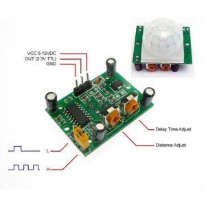
The motion sensor used is a simple device and although it operates at 5V0, it provides a 3v3 TTL output each time the sensor is triggered. This voltage drop or
disparateness can be compensated with the use of a transistor. The 3v3 is used as an input voltage to the transistor, which causes the transistor to switch on. The code
will use an inverted approach to the logic and trigger an output. What you connect to the output would be at your discretion.
Motion Sensor
The connections for the device are easy to identify and are shown in the image. The motion sensor also has a few settings which can be adjusted to suit your application; view the motion sensor's documentation to make these adjustments.
In the code below, the motion sensor's output signal provides an input or notification that the motion sensor has been triggered. The operation of the code simply
reads the input and takes action based on what is specified by the code you provide.
The example below utilises Mikroe's MikroBus coding standard, but does not implement one of their development boards so you won't need the SDK to use the code below. Although the PCB many be
powered by a 5 volt power supply, the output from the Motion Sensor is at ~3v3. This may require that you use a transistor as a switch or level tranalator to interact with the lower voltage. This does also present an inversion in the logic.
When the Motion sensor's putput goes low, it means that there has been activity ie a low is high.
                            /*
                                    Date          : May 2019.
                                    Author        : Michael A Havenga

                                Test configuration PIC :

                                    MCU             : P18F45K22
                                    Dev. Board      : BlueBerry - P40
                                    PIC Compiler ver : v7.2.0.0
                                ---
                                */

                                #define OFF 0
                                #define ON 1

                                int i;
                                int count;

                                void systemInit(){

                                   ANSELA = OFF;
                                   ANSELB = OFF;
                                   ANSELC = OFF;
                                   ANSELD = OFF;
                                   ANSELE = OFF;

                                   PORTA = 0x00;
                                   PORTB = 0x00;
                                   PORTC = 0x00;
                                   PORTD = 0x00;
                                   PORTE = 0x00;

                                   TRISA = 0b00000000;
                                   TRISB = 0b00000000;
                                   TRISC = 0b00000000;
                                   TRISD = 0b00000111;
                                   TRISE = 0b00000000;

                                   // PWM Setup and configuration
                                  C1ON_bit = 0;                       // Disable comparators
                                  C2ON_bit = 0;

                                  Delay_ms(100);
                                }

                                void applicationInit(){
                                        /*

                                        */
                                }

                                void applicationTask()
                                {
                                   if(!PORTD.B0){
	                                /*
		                                Enter your code here
	                                */

	                                }
                                }

                                void main()
                                {

                                    systemInit();
                                    applicationInit();

                                    while (1)
                                    {
                                        applicationTask();
                                    }
                                }
Build and prototype . . .
Building an embedded application has become simpler and easier to achieve. The common architecture shared by the BlueBerry (DEVCC) range of pic development boards
enables the developer to migrate the entire shield from PCB to PCB depending on the application requirements. The change in base means that the application benefits
from the new peripherals, but with no change required to connections made.
NOTE : Although PICs share common port based pinout and compatiability in the architecture, to ensure PIN compatibility it would be the responsibility of the
application developer to ensure that a PIN compatiable PIC is chosen from the same family or family of devices.